


Introduction to UML
Unified Modeling Language (UML) is a standardized modeling language consisting of an integrated set of diagrams designed to help you visualize the design and validate the architectural blueprints of a system. UML is widely used in software engineering for specifying, visualizing, constructing, and documenting the artifacts of software-intensive systems.
Key Components of UML
1. Class Diagrams

Definition: Class diagrams are static structure diagrams that show the system’s classes, their attributes and operations (or methods), and the relationships among the classes.
Key Elements:
- Classes: Represented by rectangles divided into compartments for the class name, attributes, and operations.
- Interfaces: Specify a contract that other classes can implement.
- Generalization: Shows inheritance relationships between classes.
- Dependency: Indicates that a change in one class (supplier) may affect another class (client).
- Attributes: Logical data values of an object, shown in the second compartment of the class box.
- Associations: Model relationships between classes.
- Note Symbols: Used to add comments or notes to the diagram.
Usage:
- Conceptual Perspective: Visualize a domain model.
- Software/Design Perspective: Create design class diagrams (DCD) for software design.
2. Use Case Diagrams
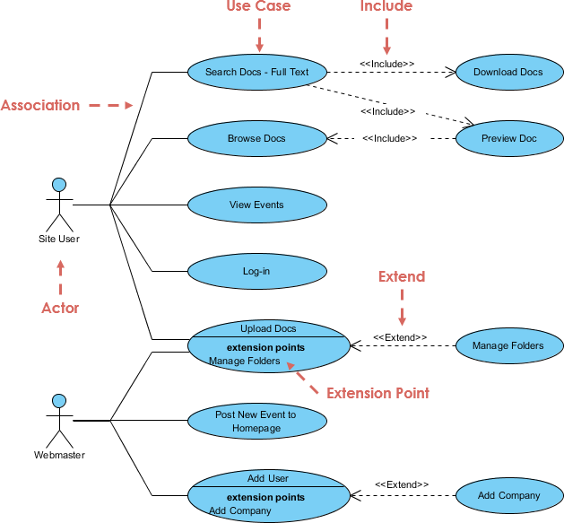
Definition: Use case diagrams capture the functional requirements of a system by illustrating the interactions between users (actors) and the system (use cases).
Key Elements:
- Actors: Represent users or external systems that interact with the system.
- Use Cases: Describe the functionalities or services offered by the system.
- Relationships: Include associations, generalizations, and dependencies.
Usage:
- Capture and document functional requirements.
- Identify system boundaries and interactions.
3. Sequence Diagrams
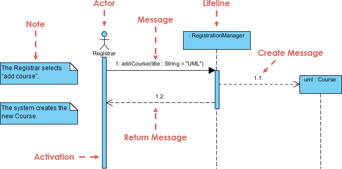
Definition: Sequence diagrams model the interaction between objects in a single scenario of a use case, focusing on the sequence of messages exchanged and the order of operations.
Key Elements:
- Lifelines: Represent objects participating in the interaction.
- Messages: Show communication between lifelines.
- Activation Bars: Indicate the duration of an operation.
Usage:
- Visualize the flow of control in a single scenario.
- Understand the dynamic behavior of the system.
4. Activity Diagrams
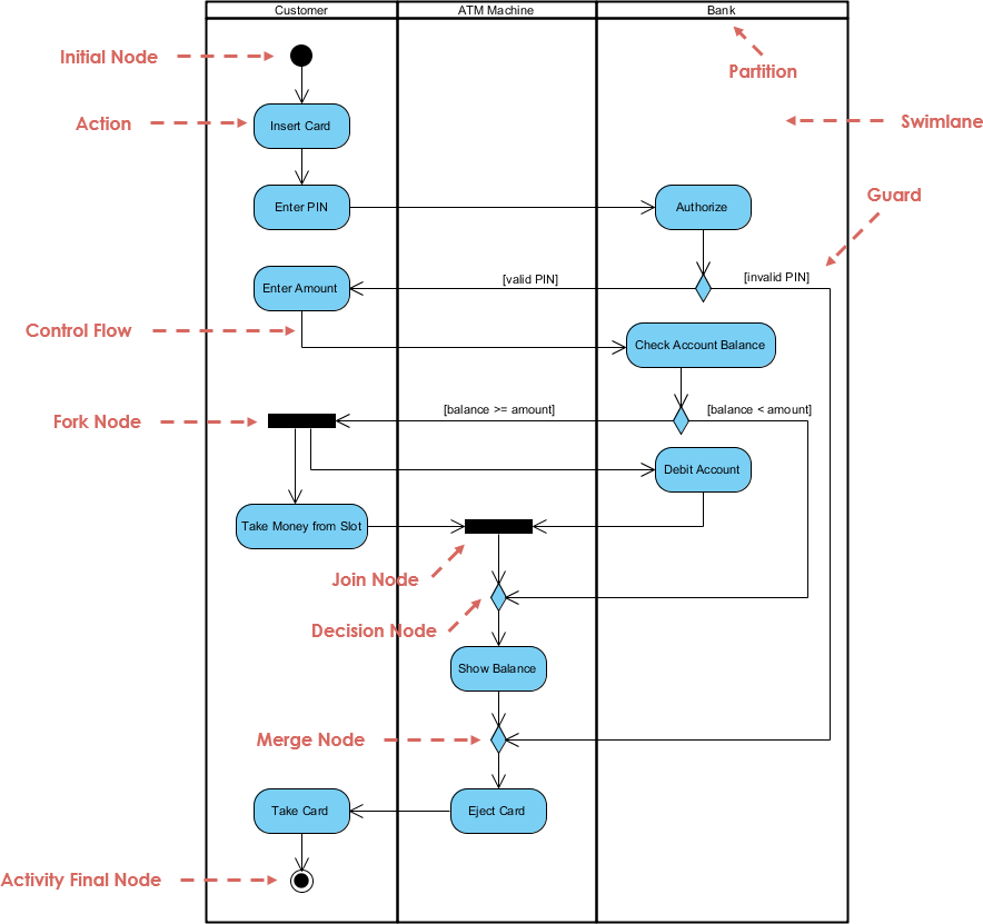
Definition: Activity diagrams model the workflow of complex operations, focusing on the sequence of activities and the flow of control.
Key Elements:
- Activities: Represent actions or operations.
- Control Flow: Shows the sequence of activities.
- Decision Nodes: Represent branching points.
- Fork/Join Nodes: Represent concurrent activities.
Usage:
- Model business processes and workflows.
- Visualize the flow of control in complex operations.
5. State Machine Diagrams
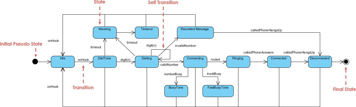
Definition: State machine diagrams model the states of an object and the transitions between those states in response to events.
Key Elements:
- States: Represent the conditions of an object.
- Transitions: Show the change from one state to another.
- Events: Trigger transitions.
Usage:
- Model the dynamic behavior of a single object.
- Visualize the lifecycle of an object.
6. Component Diagrams
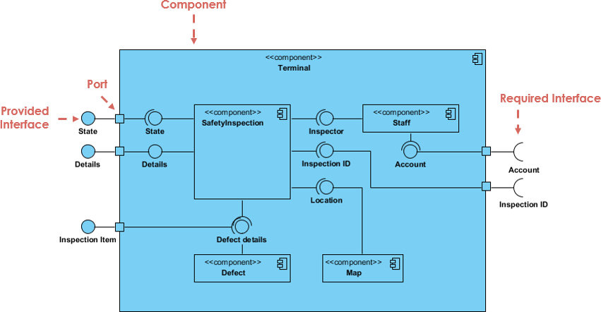
Definition: Component diagrams model the physical components of a system and their relationships, focusing on the organization and dependencies between software components.
Key Elements:
- Components: Represent physical software components.
- Interfaces: Define the services provided by components.
- Dependencies: Show relationships between components.
Usage:
- Model the physical architecture of a system.
- Visualize the organization of software components.
7. Deployment Diagrams
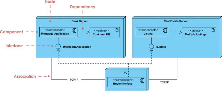
Definition: Deployment diagrams model the physical deployment of artifacts on nodes, focusing on the hardware and software configuration.
Key Elements:
- Nodes: Represent physical hardware.
- Artifacts: Represent physical software components.
- Dependencies: Show relationships between nodes and artifacts.
Usage:
- Model the physical deployment of a system.
- Visualize the hardware and software configuration.
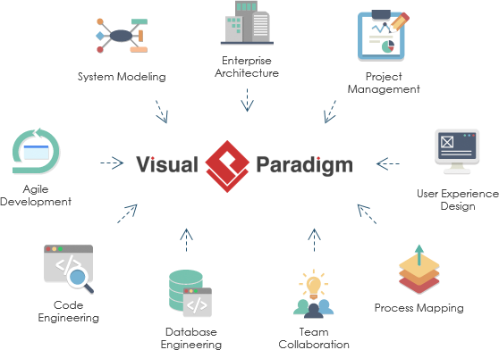
Visual Paradigm for System Modeling and Development
Visual Paradigm is a powerful modeling tool that supports UML and other modeling standards. It provides a comprehensive suite of tools for system modeling and development.
Key Features of Visual Paradigm
-
UML Diagrams:
- Supports all standard UML diagrams.
- Easy-to-use diagramming tools with drag-and-drop functionality.
-
Collaboration:
- Real-time collaboration features for team projects.
- Version control and history tracking.
-
Code Generation:
- Automatic code generation from UML models.
- Supports multiple programming languages.
-
Requirements Management:
- Integrated requirements management tools.
- Traceability between requirements and model elements.
-
Simulation and Validation:
- Simulation tools for dynamic diagrams (e.g., sequence diagrams, state machine diagrams).
- Validation tools for model consistency and correctness.
-
Documentation:
- Automatic generation of documentation from models.
- Customizable document templates.
Best Practices for Using Visual Paradigm
-
Start with Requirements:
- Capture and document requirements using use case diagrams and requirements management tools.
-
Model Static Structure:
- Use class diagrams to model the static structure of the system.
- Define classes, attributes, operations, and relationships.
-
Model Dynamic Behavior:
- Use sequence diagrams, activity diagrams, and state machine diagrams to model the dynamic behavior of the system.
- Validate the flow of control and interactions between objects.
-
Model Physical Architecture:
- Use component diagrams and deployment diagrams to model the physical architecture of the system.
- Define components, interfaces, and deployment configurations.
-
Collaborate and Review:
- Use collaboration features to work with team members.
- Regularly review and validate models with stakeholders.
-
Generate Code and Documentation:
- Use code generation tools to produce skeleton code from models.
- Generate documentation to support development and maintenance.
Conclusion
UML and Visual Paradigm provide a comprehensive set of tools for system modeling and development. By following best practices and leveraging the features of Visual Paradigm, you can effectively model and develop complex systems, ensuring consistency, traceability, and collaboration throughout the development lifecycle.
UML Resources
-
Visual Paradigm Community Edition:
- Description: Visual Paradigm Community Edition is a free UML tool widely used in academia and for non-commercial purposes. It supports various UML diagrams and offers a user-friendly interface.
- Features:
- Supports UML 2.x and ERD for database modeling.
- Provides a comprehensive set of UML diagram examples and templates.
- Offers a vibrant community circle for support and learning resources.
- Usage: Ideal for students, educators, and individuals exploring UML for personal projects.
- References: 1, 2, 3, 4, 5.
-
Visual Paradigm Modeler:
- Description: Visual Paradigm Modeler is an award-winning UML tool that supports a wide range of modeling standards, including UML, BPMN, ERD, and DFD.
- Features:
- Easy-to-use interface for fast and simple modeling.
- Supports collaboration and teamwork with traceable UML diagrams and models.
- Interlinks UML models with sub-diagrams and other development tools.
- Usage: Suitable for software development teams and large-scale projects.
- References: 6, 7.
-
Resource Catalog:
- Description: The Resource Catalog in Visual Paradigm is a powerful feature that enhances modeling efficiency and quality.
- Features:
- Allows users to establish linkages among UML model elements and external resources.
- Provides element referencing and reuse capabilities.
- Ensures design correctness with syntax checking and consistency validation.
- Usage: Essential for creating high-quality UML diagrams and maintaining model integrity.
- References: 3, 4.
-
Collaboration and Integration:
- Description: Visual Paradigm supports collaboration and integration with various development tools and platforms.
- Features:
- Enables team collaboration with shared UML models and project hosting.
- Integrates with code engineering, process simulation, and other development tools.
- Supports cross-platform compatibility (Windows, Mac OS X, Linux).
- Usage: Facilitates collaborative software development and streamlines the development process.
- References: 6, 8, 7.
-
Learning Resources and Community Support:
- Description: Visual Paradigm offers a wealth of learning resources and community support to help users get started with UML modeling.
- Features:
- Provides free learning resources, including tutorials, examples, and templates.
- Offers community support through the VP Community Circle.
- Supports users with a comprehensive user guide and documentation.
- Usage: Ideal for beginners and experienced users looking to enhance their UML modeling skills.
- References: 1, 2, 4, 9.
These resources provide a comprehensive overview of the features and benefits of adopting the Visual Paradigm UML tool for various modeling and development needs.
UML Class Diagram Resources
Here is a resource list for learning how to use class diagrams with Visual Paradigm:
-
Visual Paradigm Guides and Tutorials:
- How to Draw Class Diagram: This guide provides step-by-step instructions on creating class diagrams using Visual Paradigm. It covers the basics of class diagrams and how to use the tool’s features to create them efficiently10.
- Class Diagram in Visual Paradigm: This resource offers a comprehensive guide on creating class diagrams, including how to add classes, attributes, operations, and relationships11.
- UML Class Diagram Tutorial: A detailed tutorial that explains the concepts of class diagrams and how to create them using Visual Paradigm. It includes examples and best practices for effective modeling12.
- Step-by-Step Class Diagram Tutorial: This tutorial walks you through the process of creating a class diagram using Visual Paradigm, from opening the tool to adding multiplicity and roles to associations13.
- Generate Class Diagram from Existing Classes: This article explains how to generate class diagrams from existing classes in Visual Paradigm, which can be useful when starting from scratch or reusing elements14.
-
External Learning Resources:
- Learning Class Diagrams with Visual Paradigm: This article from ArchiMetric provides insights into creating and managing class diagrams using Visual Paradigm, highlighting its ease of use and comprehensive features15.
- Lab: Creating Class Diagrams in Visual Paradigm: This lab guide from James Madison University offers practical steps for creating class diagrams in Visual Paradigm, including tips on colors, fonts, icons, and exporting diagrams16.
-
Additional Resources:
- Visual Paradigm Online: Visual Paradigm Online offers a free edition for creating class diagrams and other UML diagrams. It provides an intuitive interface, rich formatting options, and cross-platform compatibility18.
- Visual Paradigm Blog: The Visual Paradigm blog features articles and tutorials on various UML diagrams, including class diagrams. It provides practical examples and tips for effective modeling13.
These resources will help you get started with creating class diagrams using Visual Paradigm, from understanding the basics to advanced techniques for effective modeling.