


In the realm of software development, Unified Modeling Language (UML) diagrams play a crucial role in visualizing and designing systems. Two essential types of UML diagrams are Class Diagrams and Object Diagrams. While both are used for modeling, they serve different purposes and offer unique insights into a system’s structure and behavior. This article explores the distinctions between Class and Object Diagrams, their uses, and how to create them using tools like Visual Paradigm.

Class Diagrams
Overview
A Class Diagram provides a high-level, static view of a system’s structure. It focuses on describing the classes, interfaces, and their relationships, including attributes, methods, associations, generalizations, and dependencies. Essentially, a Class Diagram serves as a blueprint for the system, illustrating the common features and rules of a set of objects.

Key Features
- Static View: Class Diagrams offer a timeless perspective of the system, focusing on the structure rather than the runtime behavior.
- Components:
- Classes: Represent the main building blocks, encapsulating attributes and methods.
- Relationships: Include associations (connections between classes), generalizations (inheritance), and dependencies (usage relationships).
- Purpose: Class Diagrams are used for system design, architecture planning, and code generation. They help developers understand the system’s structure and plan its implementation.
Example
Consider a simple library management system:
- Classes:
Book,Member,Loan - Attributes:
Book: title, author, ISBNMember: name, memberIDLoan: loanID, loanDate, returnDate
- Methods:
Book: checkAvailability()Member: register(), borrowBook(), returnBook()Loan: calculateFine()
- Relationships:
- A
Membercan borrow multipleBooksthroughLoan. - Each
Loanis associated with oneBookand oneMember.
- A
Creating Class Diagrams in Visual Paradigm
- Start a New Diagram: Select
Diagram > Newand chooseClass Diagram. - Add Classes: Use the toolbar to add classes to the diagram.
- Define Attributes and Methods: Double-click on a class to add attributes and methods.
- Create Relationships: Use the toolbar to create associations, generalizations, and dependencies between classes.
Object Diagrams
Overview
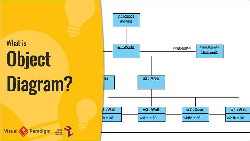
An Object Diagram shows a snapshot of the system at a specific point in time. It focuses on instances (objects) and their relationships, including the values of attributes and the links between objects. Object Diagrams provide a concrete and specific view of how objects interact at runtime.
Key Features
- Dynamic View: Object Diagrams capture the state of the system at a particular moment, illustrating runtime behavior.
- Components:
- Objects: Instances of classes with specific attribute values.
- Links: Connections between objects representing their interactions.
- Purpose: Object Diagrams are valuable for testing, debugging, and illustrating scenarios. They help in understanding how the system behaves in real-time situations.
Example
Using the library management system example:
- Objects:
Book: “The Great Gatsby” by F. Scott Fitzgerald, ISBN 9780743273565Member: John Doe, memberID 12345Loan: loanID 67890, loanDate 2023-10-01, returnDate 2023-10-15
- Links:
- John Doe has borrowed “The Great Gatsby” through loanID 67890.
Creating Object Diagrams in Visual Paradigm
- Start a New Diagram: Select
Diagram > Newand chooseObject Diagram. - Add Objects: Use the toolbar to add objects to the diagram.
- Define Attribute Values: Double-click on an object to set specific attribute values.
- Create Links: Use the toolbar to create links between objects, representing their interactions.
Key Differences Between Class and Object Diagrams
| Feature | Class Diagram | Object Diagram |
|---|---|---|
| Focus | Structure of classes and their relationships | Instances and their relationships at a specific time |
| Level of Detail | Abstract, general | Concrete, specific |
| Time Perspective | Static, timeless | Dynamic, runtime |
| Purpose | Design, architecture, code generation | Testing, debugging, illustrating scenarios |
| Stability | Stable, consistent | Dynamic, variable |
| Abstraction | High | Low |
Conclusion
Class Diagrams and Object Diagrams are essential tools in UML for modeling different aspects of a software system. Class Diagrams provide a general blueprint, focusing on the structure and relationships between classes. In contrast, Object Diagrams capture specific runtime scenarios, illustrating how objects interact at a particular moment. Both diagram types contribute to a comprehensive understanding of a system’s architecture and behavior, aiding in design, testing, and debugging. Tools like Visual Paradigm support the creation of these diagrams, making the modeling process more efficient and effective.
References
- What is the difference between a class diagram vs an object diagram? Stack Overflow
- Learning Class Diagrams with Visual Paradigm. Archimetric
- Class Diagrams Overview. UML Diagrams
- Visual Paradigm Environment. Angelfire
- Class Diagrams vs Object Diagrams in UML. Visual Paradigm
- Drawing Class Diagrams. Visual Paradigm
- Unveiling UML: Navigating the Differences Between Object Diagrams and Class Diagrams. Visual Paradigm
- Step-by-Step Class Diagram Tutorial Using Visual Paradigm. Visual Paradigm Blog
- What are the key differences between UML class diagrams? LinkedIn
- Visual Paradigm Tutorial. YouTube