
Introduction
Visual Paradigm is a versatile modeling tool that supports both UML (Unified Modeling Language) and SysML (Systems Modeling Language). This tutorial will guide you through the essentials of using Visual Paradigm for both UML and SysML, providing practical examples and insights into how these modeling languages can enhance your system and software development processes.
Introduction to SysML
SysML (Systems Modeling Language) is an extension of UML (Unified Modeling Language) tailored for systems engineering. It provides a robust framework for modeling complex systems, including hardware, software, personnel, and facilities. Visual Paradigm is a versatile modeling tool that supports SysML, offering a comprehensive suite of features to facilitate system model creation and management. This guide will walk you through the essential aspects of using SysML in Visual Paradigm, from basic diagram creation to advanced modeling techniques.
Getting Started with SysML in Visual Paradigm
Installation and Setup
- Download and Install: Visit the Visual Paradigm website to download the software. Follow the installation instructions for your operating system.
- Create a New Project: Open Visual Paradigm and create a new project. Choose SysML as the modeling language for your project.
Understanding SysML Diagrams
SysML includes nine types of diagrams, each serving a specific purpose in system modeling:
- Requirement Diagram: Captures and organizes system requirements, ensuring traceability throughout the development lifecycle.
- Use Case Diagram: Illustrates system functionality from a user’s perspective, showing interactions between users (actors) and the system.
- Block Definition Diagram (BDD): Defines system components and their relationships, similar to UML class diagrams but more flexible.
- Internal Block Diagram (IBD): Shows the internal structure of a block, including parts, ports, and connectors.
- Parametric Diagram: Models constraints and performance parameters, helping to ensure the system meets measurable criteria.
- Sequence Diagram: Displays how objects interact in a particular scenario, focusing on the time-ordering of messages.
- State Machine Diagram: Represents the states of an object and transitions caused by events.
- Activity Diagram: Models workflows of stepwise activities and actions within a system.
- Package Diagram: Organizes model elements into packages, providing a way to manage and structure complex models.
Creating SysML Diagrams in Visual Paradigm
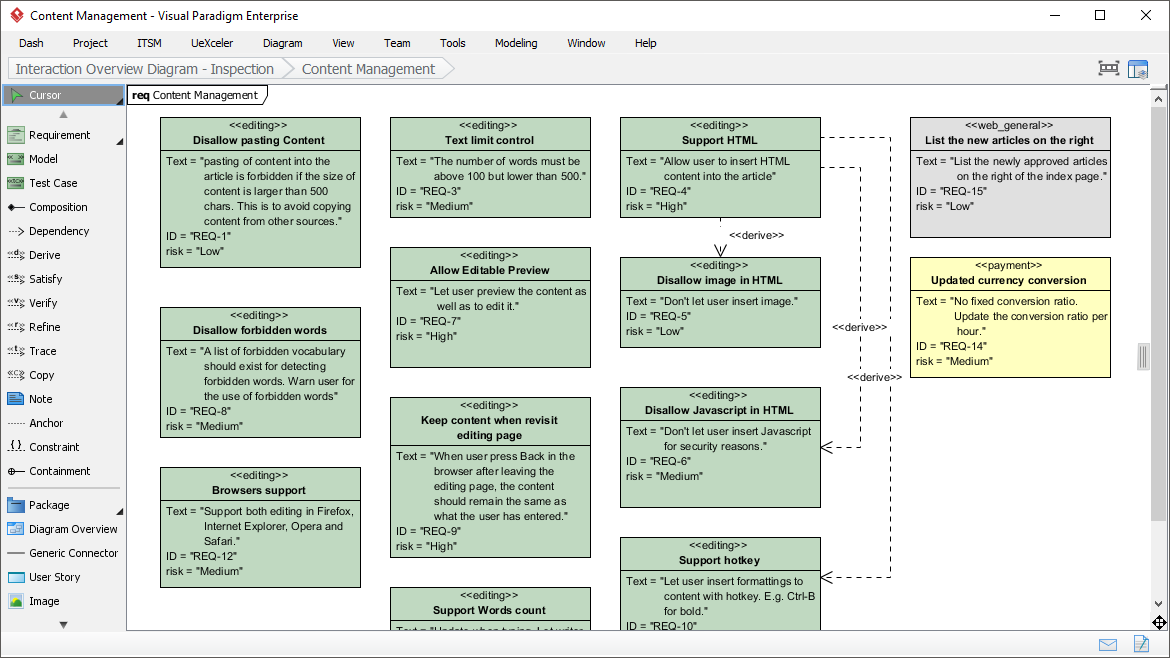
Requirement Diagram
- Open Requirement Diagram Tool: In your project, select “Requirement Diagram” from the diagram options.
- Add Requirements: Drag and drop requirements onto the canvas.
- Define Relationships: Use connectors to show relationships between requirements, such as containment, derivation, and satisfaction.
Example: Modeling Requirements for a Smart Home System
- Requirements:
Security,Energy Efficiency,User Interface - Relationships:
SecuritycontainsIntrusion Detection,Energy EfficiencyincludesSmart LightingandThermostat Control
Block Definition Diagram (BDD)
- Open BDD Tool: Select “Block Definition Diagram” from the diagram options.
- Add Blocks: Drag and drop blocks onto the canvas. Define properties and operations for each block.
- Define Relationships: Use connectors to define relationships between blocks, such as associations, compositions, and generalizations.
Example: Modeling Components of an Electric Vehicle
- Blocks:
Battery,Motor,Controller - Relationships:
ControllermanagesMotorandBattery
Internal Block Diagram (IBD)
- Open IBD Tool: Select “Internal Block Diagram” from the diagram options.
- Add Parts: Drag and drop parts onto the canvas. Define ports and connectors for each part.
- Define Internal Structure: Use connectors to show the internal structure of a block, including parts, ports, and connectors.
Example: Internal Structure of a Robotic Arm
- Parts:
Base,Arm,Gripper - Connectors:
ArmconnectsBaseandGripperthrough joints
Understanding UML and SysML
UML (Unified Modeling Language)
UML is a standardized modeling language used primarily in software engineering to visualize the design and structure of a system. It consists of various diagrams that help in modeling both static and dynamic aspects of software systems.

Key UML Diagrams:
- Class Diagram: Represents the static structure of a system by showing its classes, attributes, methods, and relationships.
- Use Case Diagram: Captures the functional requirements of a system by showing interactions between users (actors) and the system.
- Sequence Diagram: Displays how objects interact in a particular scenario of a use case, focusing on the time-ordering of messages.
- Activity Diagram: Models workflows of stepwise activities and actions within a system.
- State Machine Diagram: Represents the states of an object and transitions caused by events.
SysML (Systems Modeling Language)
SysML is an extension of UML tailored for systems engineering. It addresses a broader range of systems, including hardware, software, personnel, and facilities.
Key SysML Diagrams:
- Requirement Diagram: Captures requirements and their relationships, ensuring traceability throughout the system lifecycle.
- Parametric Diagram: Models constraints and performance parameters, helping to ensure the system meets measurable criteria.
- Block Definition Diagram: Defines system components and their relationships, similar to UML class diagrams but more flexible.
- Internal Block Diagram: Shows the internal structure of a block, including parts, ports, and connectors.
Getting Started with Visual Paradigm
Installation and Setup
- Download and Install: Visit the Visual Paradigm website to download the software. Follow the installation instructions for your operating system.
- Create a New Project: Open Visual Paradigm and create a new project. Choose the type of diagram you want to create (UML or SysML).
Creating UML Diagrams
Class Diagram Example
- Open Class Diagram Tool: In your project, select “Class Diagram” from the diagram options.
- Add Classes: Drag and drop classes onto the canvas. Define attributes and methods for each class.
- Define Relationships: Use connectors to define relationships between classes, such as associations, generalizations, and dependencies.
Example: Modeling a Library System
- Classes:
Book,Member,Loan - Attributes:
Book(title, author, ISBN),Member(name, memberID),Loan(loanID, loanDate) - Relationships:
Membercan borrow multipleBooksthroughLoan
Sequence Diagram Example
- Open Sequence Diagram Tool: Select “Sequence Diagram” from the diagram options.
- Add Actors and Objects: Drag and drop actors and objects onto the canvas.
- Define Interactions: Use messages to show interactions between objects over time.
Example: Online Shopping Process
- Actors:
Customer,ShoppingCart,PaymentGateway - Interactions:
Customeradds items toShoppingCart, proceeds to checkout, and interacts withPaymentGateway
Creating SysML Diagrams
Requirement Diagram Example
- Open Requirement Diagram Tool: Select “Requirement Diagram” from the diagram options.
- Add Requirements: Drag and drop requirements onto the canvas.
- Define Relationships: Use connectors to show relationships between requirements, such as containment, derivation, and satisfaction.
Example: Requirements for an Autonomous Vehicle
- Requirements:
Safety,Performance,User Interface - Relationships:
SafetycontainsEmergency Braking,PerformanceincludesSpeedandFuel Efficiency
Parametric Diagram Example
- Open Parametric Diagram Tool: Select “Parametric Diagram” from the diagram options.
- Add Constraints: Drag and drop constraints onto the canvas.
- Define Parameters: Use connectors to show relationships between constraints and parameters.
Example: Performance Constraints for a Drone
- Constraints:
Maximum Speed,Battery Life - Parameters:
Wind Resistance,Payload Weight
Advanced Features in Visual Paradigm
Model Transformation
Visual Paradigm supports model transformation, allowing you to refine and reuse models. This feature ensures that your models are reliable and traceable throughout the development lifecycle.
Collaboration Tools
Visual Paradigm facilitates team collaboration with features like real-time editing, version control, and commenting. This makes it an ideal tool for agile development teams.
Integration with Other Standards
Visual Paradigm supports a wide range of modeling standards, including ERD (Entity-Relationship Diagrams) and BPMN (Business Process Model and Notation). This integration allows you to map process flows and enhance your design capabilities.
Conclusion
SysML modeling with Visual Paradigm offers a comprehensive and flexible approach to systems engineering. By leveraging its advanced features and collaboration tools, you can enhance communication, streamline project management, and ensure the success of your development projects. Whether you are modeling requirements, defining system components, or visualizing internal structures, Visual Paradigm provides the tools you need to create high-quality system models.
Visual Paradigm is a powerful tool for both UML and SysML modeling, offering a comprehensive set of features that cater to the needs of software and systems engineering. By leveraging its advanced features and collaboration tools, you can enhance communication, streamline project management, and ensure the success of your development projects.
References
- Visual Paradigm SysML Guide
- Visual Paradigm Online SysML Tool
- Visual Paradigm SysML Modeling Tools
- Visual Paradigm Features
- SysML Forum Review
- Visual Paradigm Full Features PDF
- Visual Paradigm MBSE and SysML Guide
- OOSE SysML Tools
- Visual Paradigm SysML Overview
- Visual Paradigm Online SysML BDD Tool
This guide provides a foundational understanding of SysML modeling using Visual Paradigm, along with practical examples to help you get started.